This project wires an MPU6050 gyro/accelerometer to a NodeMCU ESP8266, shows live status on a 0.96″ I²C OLED, optionally reads a DHT11, and streams quaternion “teapot” packets so a Processing sketch can render the board’s orientation in 3D.
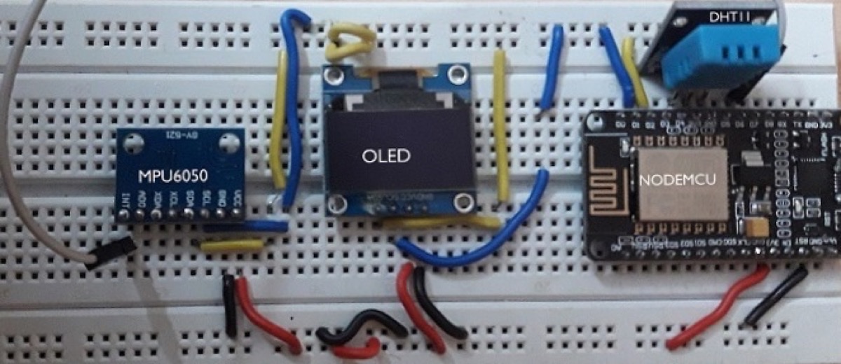
Hardware
- NodeMCU ESP8266 board
- MPU6050 gyro / accelerometer module
- 0.96″ I²C OLED (SSD1306, 128×64)
- DHT11 temperature & humidity sensor (optional expansion)
- Jumpers / breadboard
Software: Arduino IDE · Processing (+ toxiclibs) · IoT cloud hooks as needed
NodeMCU ESP8266
NodeMCU is open-source firmware paired with DIP-style prototyping boards that combine a USB interface with an ESP-12 / ESP8266 Wi-Fi SoC (Tensilica Xtensa LX106). The DIP form factor is friendly on a breadboard and common in IoT builds.
MPU6050
The MPU6050 is a MEMS package with a 3-axis accelerometer, 3-axis gyroscope, and an onboard Digital Motion Processor (DMP). 16-bit ADCs capture 3D motion; I²C talks to the MCU. Typical uses include drones, self-balancing robots and RC vehicles.
Module pins
| Pin | Role |
|---|---|
| INT | Interrupt digital output |
| AD0 | I²C address LSB (tie to VCC to flip slave address) |
| XCL / XDA | Auxiliary I²C clock / data for other sensors |
| SCL / SDA | Primary I²C to the microcontroller |
| GND / VCC | Ground / supply (module often run from 5 V or 3.3 V per board design) |
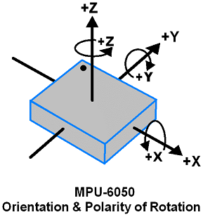
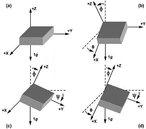
Gyroscope — rotational velocity about X, Y, Z.
Accelerometer — tilt / inclination about X, Y, Z.
OLED (SSD1306 0.96″)
| Feature | Detail |
|---|---|
| Panel | Monochrome SSD1306, ~0.96″ |
| Resolution | 128×64, wide viewing angle |
| Supply | 3 V–5 V (5 V and 3.3 V logic friendly) |
| Bus | SPI or I²C |
| Extras | Bitmap graphics; Arduino libraries available |
Typical 7-pin mapping
| # | Name | Notes |
|---|---|---|
| 1 | GND | Circuit ground |
| 2 | Vdd / Vcc | 3.3 V or 5 V |
| 3 | SCK / SCL / D0 | Clock (I²C or SPI) |
| 4 | SDA / MOSI / D1 | Data |
| 5 | RES / RST | Hold low briefly to reset |
| 6 | DC / A0 | Command / data select |
| 7 | CS | Chip select (multi-SPI) |
Circuit
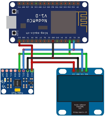
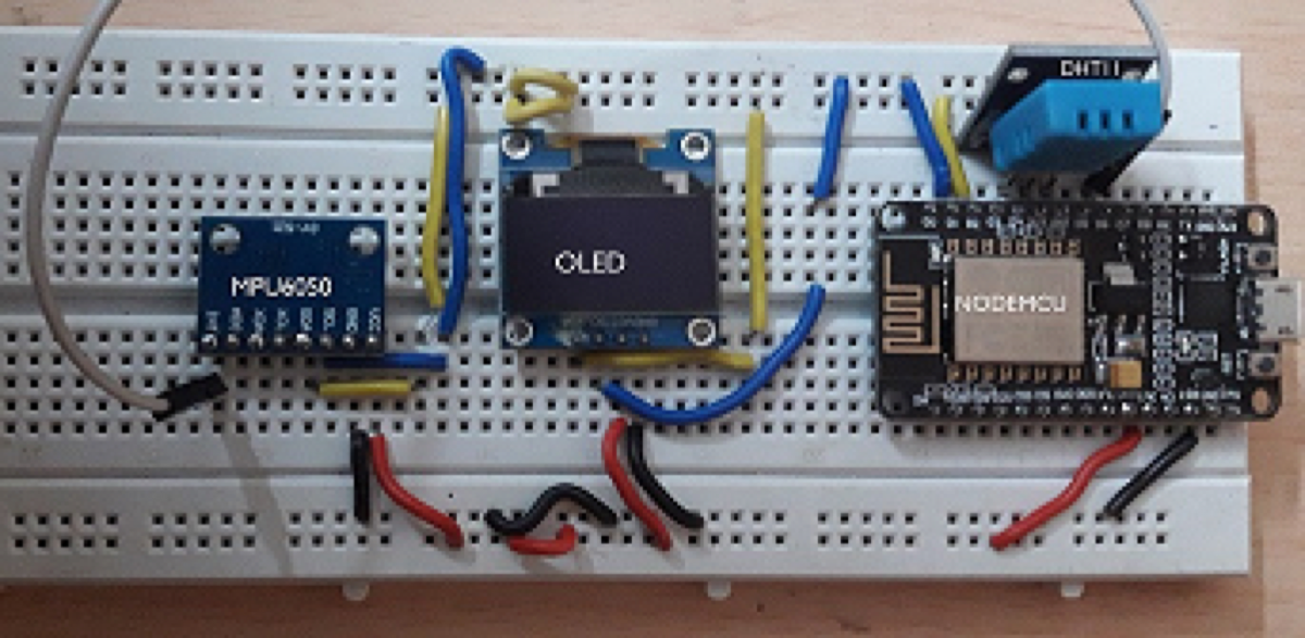
I²C for MPU and OLED (SCL/SDA on the NodeMCU), interrupt from MPU on D6, activity LED on D7, optional DHT11 on a digital pin. Sample and final wiring:
Processing visualiser
Processing is an open Java-based creative coding IDE (ancestor of ideas behind Arduino and p5.js). For the 3D orientation demo, install Processing and toxiclibs, then open a serial port to the NodeMCU (115200 baud) and parse InvenSense teapot packets into a quaternion-driven model.
Firmware outline (NodeMCU)
Core idea: initialise OLED + Wi-Fi + DHT, bring up MPU DMP, then either show connection / climate on the OLED or stream teapot packets for Processing.
#include <Wire.h>
#include <Adafruit_GFX.h>
#include <Adafruit_SSD1306.h>
#include <ESP8266WiFi.h>
#include <Adafruit_Sensor.h>
#include <DHT.h>
#include <DHT_U.h>
#include "I2Cdev.h"
#include "MPU6050_6Axis_MotionApps20.h"

MPU6050 mpu;
#define OUTPUT_TEAPOT
#define INTERRUPT_PIN D6
#define LED_PIN D7
#define SCREEN_WIDTH 128
#define SCREEN_HEIGHT 64
#define OLED_RESET -1
#define DHTPIN 2
#define DHTTYPE DHT11

DHT_Unified dht(DHTPIN, DHTTYPE);
Adafruit_SSD1306 display(SCREEN_WIDTH, SCREEN_HEIGHT, &Wire, OLED_RESET);

bool dmpReady = false;
uint8_t fifoBuffer[64];
uint8_t teapotPacket[14] = { '$', 0x02, 0,0, 0,0, 0,0, 0,0, 0x00, 0x00, '\r', '\n' };
volatile bool mpuInterrupt = false;
boolean conflag = 0;

void ICACHE_RAM_ATTR dmpDataReady() { mpuInterrupt = true; }

void setup() {
  Serial.begin(115200);
  dht.begin();
  display.begin(SSD1306_SWITCHCAPVCC, 0x3C);
  // splash / Wi-Fi connect status on OLED…

  Wire.begin();
  Wire.setClock(400000);
  mpu.initialize();
  pinMode(INTERRUPT_PIN, INPUT);
  uint8_t devStatus = mpu.dmpInitialize();
  if (devStatus == 0) {
    mpu.CalibrateAccel(6);
    mpu.CalibrateGyro(6);
    mpu.setDMPEnabled(true);
    attachInterrupt(digitalPinToInterrupt(INTERRUPT_PIN), dmpDataReady, RISING);
    dmpReady = true;
  }
  pinMode(LED_PIN, OUTPUT);
}

void loop() {
  if (conflag == 0) {
    // OLED: Wi-Fi status + DHT temperature / humidity
    // set conflag = 1 once linked
  } else {
    if (!dmpReady) return;
    if (mpu.dmpGetCurrentFIFOPacket(fifoBuffer)) {
#ifdef OUTPUT_TEAPOT
      teapotPacket[2] = fifoBuffer[0];
      teapotPacket[3] = fifoBuffer[1];
      teapotPacket[4] = fifoBuffer[4];
      teapotPacket[5] = fifoBuffer[5];
      teapotPacket[6] = fifoBuffer[8];
      teapotPacket[7] = fifoBuffer[9];
      teapotPacket[8] = fifoBuffer[12];
      teapotPacket[9] = fifoBuffer[13];
      Serial.write(teapotPacket, 14);
      teapotPacket[11]++;
#endif
      digitalWrite(LED_PIN, !digitalRead(LED_PIN));
    }
  }
}
Libraries used in the full sketch include Adafruit DHT / Unified Sensor / GFX / SSD1306, ESP8266WiFi, and Jeff Rowberg’s I2Cdev / MPU6050 MotionApps stack.
Processing sketch outline
import processing.serial.*;
import processing.opengl.*;
import toxi.geom.*;
import toxi.processing.*;

ToxiclibsSupport gfx;
Serial port;
char[] teapotPacket = new char[14];
float[] q = new float[4];
Quaternion quat = new Quaternion(1, 0, 0, 0);

void setup() {
  size(600, 600, OPENGL);
  gfx = new ToxiclibsSupport(this);
  port = new Serial(this, "COM4", 115200); // use your port
  port.write('r');
}

void draw() {
  background(0);
  pushMatrix();
  translate(width / 2, height / 2);
  float[] axis = quat.toAxisAngle();
  rotate(axis[0], -axis[1], axis[3], axis[2]);
  fill(255, 0, 0, 200);
  box(386, 40, 200);
  fill(255);
  text("https://subhdb.co.in", -183, 10, 101);
  popMatrix();
}

// serialEvent(): sync on '$', assemble 14-byte teapot packet,
// decode q0..q3 from bytes, quat.set(q[0], q[1], q[2], q[3]);
Replace COM4 with the NodeMCU serial device on your machine. Tilt the breadboard and the on-screen model should follow.
Watch it move
Original demo (also on my YouTube channel):
References
- Tags from the original post:
#gyro·#accelerometer·#iot·#nodemcu·#processing - Related: A complete home automation solution framework using Hassio · Measure flow rates using Particle Photon
This piece was first published on 9 May 2020 as Visualize NODEMCU plugged MPU6050's realtime movement in OLED display, and is carried here under Technology as part of the digital journey archive.
Filed under
- NodeMCU
- MPU6050
- OLED
- Processing
- IoT
- Sensors