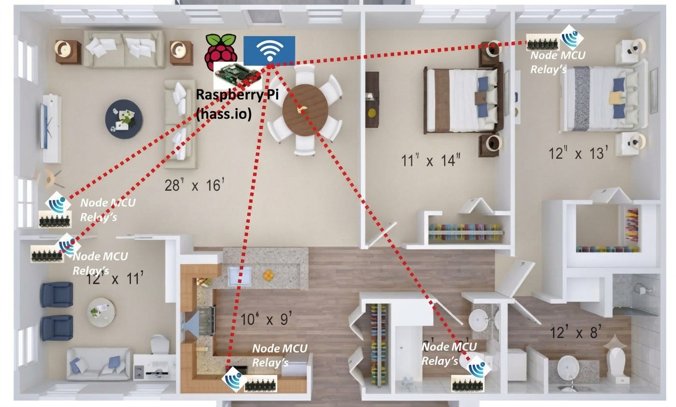
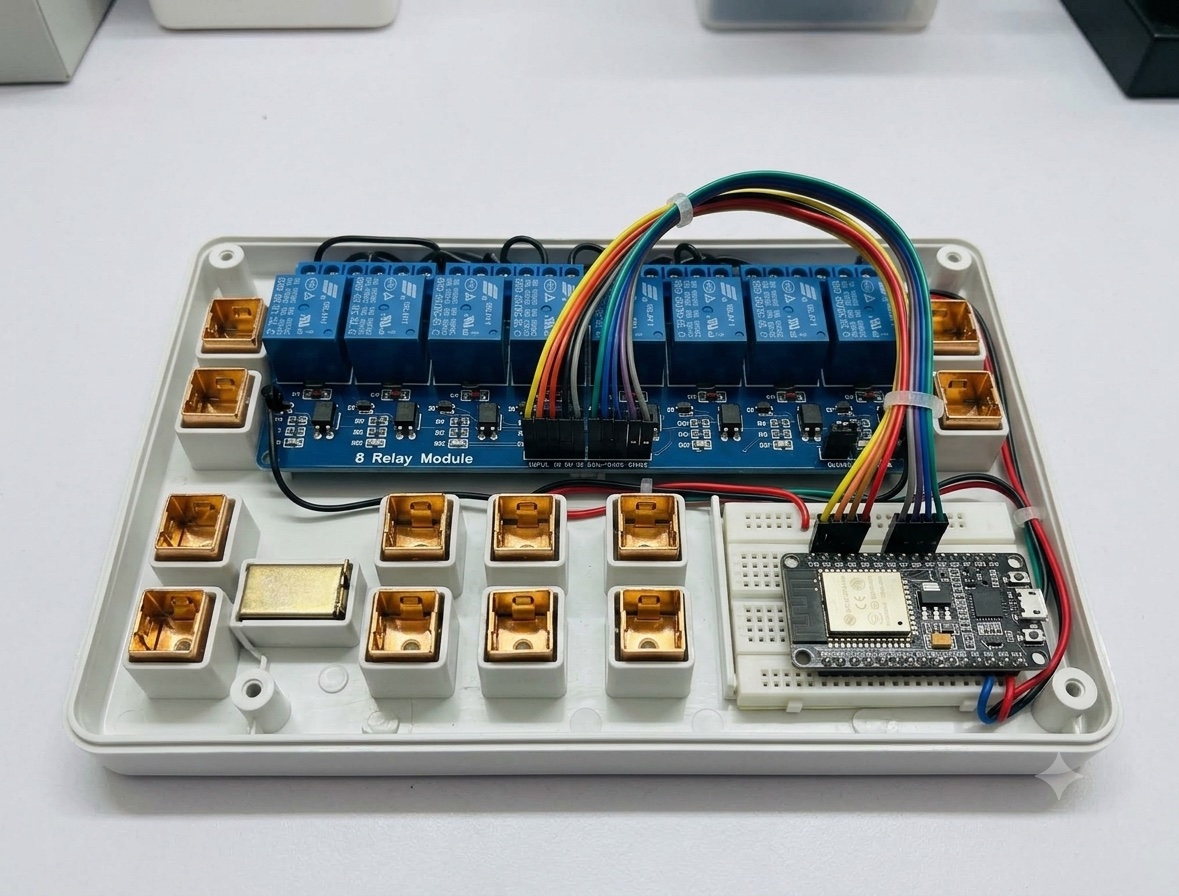
This is a framework, not a one-off demo: a Raspberry Pi running Hass.io (Home Assistant) as the central hub, MQTT (and optionally WebSockets) for messaging, a NodeMCU talking to an 8-channel relay, and eight plug points for a room’s loads. More devices plug into the same pattern later.
What the framework is
Beyond a sample “toggle one light” sketch, this stack is meant to grow: MQTT for robust Home Assistant integration, WebSockets for a local NodeMCU-hosted UI, and a Pi that stays the centre of communications for every new sensor or actuator you add.
| Layer | Role |
|---|---|
| Raspberry Pi + Hass.io | Hub — UI, automations, entity registry |
| Mosquitto MQTT | Message bus (configured on port 8183 in this build) |
| ESPHome / NodeMCU firmware | Edge controller for relays |
| 8-channel relay + plugs | Switched mains for up to eight room circuits |
Components
- Raspberry Pi (one)
- NodeMCU
- 3.3 V and 5 V power-supply module
- 8-channel relay
- 8 electrical plug points (one room — in my case, the bedroom)
- Jumper cables
Software on the Pi
- Install the Hass.io image on the Raspberry Pi
- Configure ESPHome and the Mosquitto broker (MQTT)
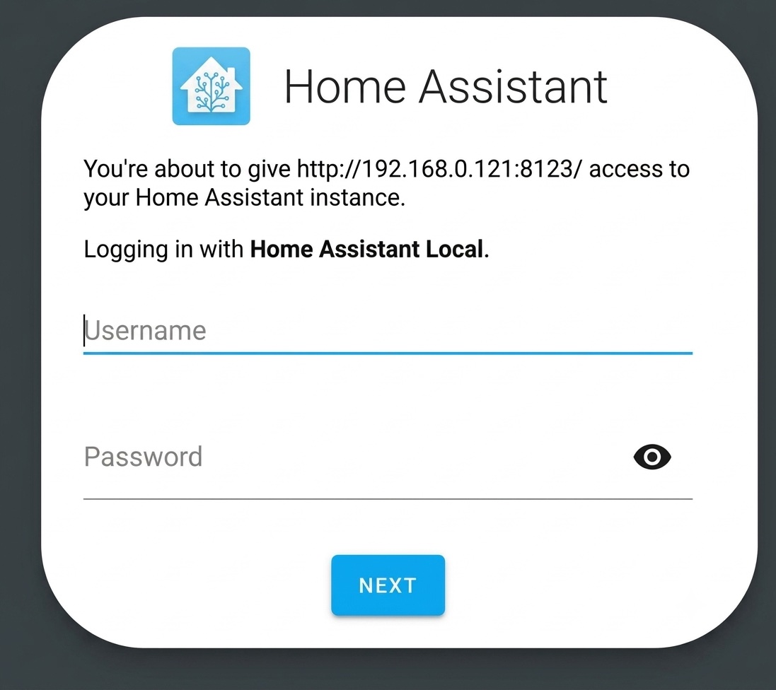
- Start MQTT on the default port used in this project: 8183
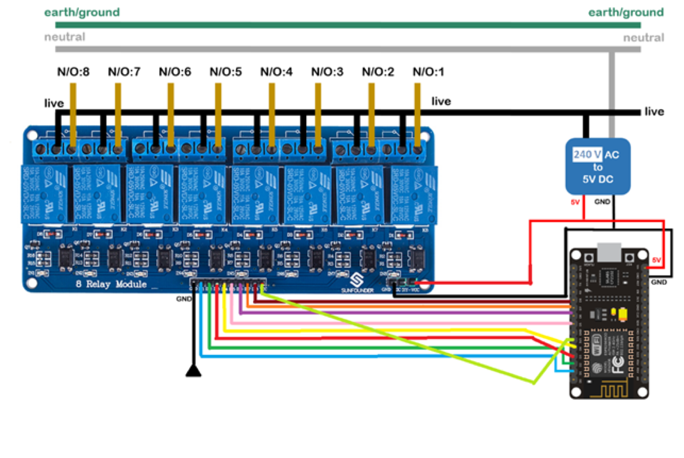
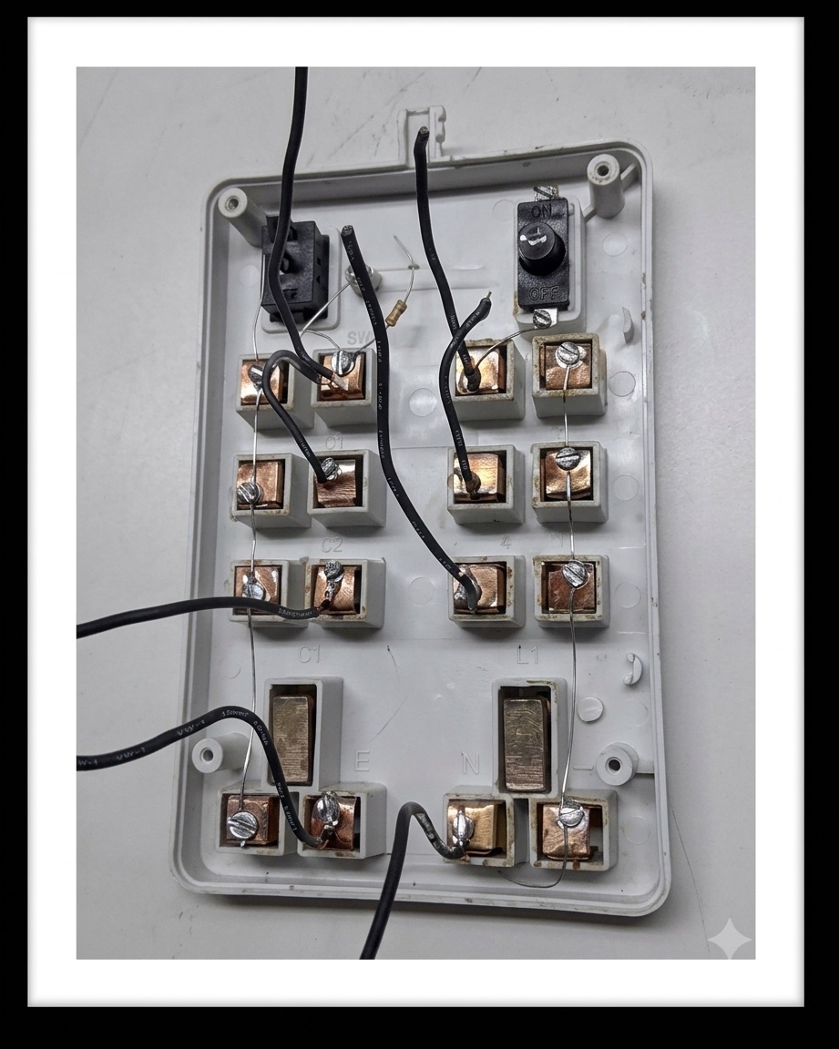
Then prepare the NodeMCU, relay module, and electrical mains circuit for the sample room.
NodeMCU WebSocket UI (optional local page)
If you want a webpage on the NodeMCU as well as the Home Assistant UI:
- Create
index.html,style.css, andscript.jsfor the WebSocket site - Minify CSS and JS (e.g. with node-minify)
- Inline the minified assets into
index.html, then minify the HTML - Gzip the result with 7z — in my case ~3 KB after compression (from ~13 KB of source HTML/JS/CSS)
- Convert the gzip bytes to a C/C++ hex blob (for
indexhtml.h) - Include that header from the main
.ino
That keeps a usable mobile UI even when you hit the NodeMCU’s static IP directly.
Relay pin map (no PCF8574)
I did not use a PCF8574AP expander. Relay GPIO mapping on the NodeMCU:
| Relay | GPIO | NodeMCU label |
|---|---|---|
| 1 | 5 | D1 |
| 2 | 4 | D2 |
| 3 | 0 | D3 |
| 4 | 2 | D4 |
| 5 | 14 | D5 |
| 6 | 12 | D6 |
| 7 | 13 | D7 |
| 8 | 15 | D8 |
uint8_t RelayName(uint8_t pinno) {
  uint8_t relaynm;
  if (pinno == 0) relaynm = 5;
  else if (pinno == 1) relaynm = 4;
  else if (pinno == 2) relaynm = 0;
  else if (pinno == 3) relaynm = 2;
  else if (pinno == 4) relaynm = 14;
  else if (pinno == 5) relaynm = 12;
  else if (pinno == 6) relaynm = 13;
  else if (pinno == 7) relaynm = 15;
  return relaynm;
}
The MQTT/Hass.io NodeMCU sketch followed the community pattern popularised by Debashish Sahu, adapted for direct GPIO instead of the PCF8574.
Static IP on the NodeMCU
To avoid DHCP churn:
IPAddress local_IP(192, 168, 0, 112);
IPAddress gateway(192, 168, 0, 1);
IPAddress subnet(255, 255, 255, 0);
IPAddress primaryDNS(8, 8, 8, 8);
IPAddress secondaryDNS(8, 8, 4, 4);

WiFi.mode(WIFI_STA);
WiFi.config(local_IP, gateway, subnet, primaryDNS, secondaryDNS);
After the NodeMCU boots with this firmware the first time, it registers the relay entities in Home Assistant. Put those entities on a Lovelace dashboard and you can drive the room from Hass.io. Prefer the NodeMCU page instead? Open the static IP from a phone browser.
Alternative: mobile / IR without the Pi
If you only need simple start/stop from a phone (or remote) and do not need a full MQTT architecture, drop the Raspberry Pi and Hass.io. Keep:
- NodeMCU
- 3.3 V / 5 V power module
- 8-channel relay
- 8 plug points
- Jumpers
Optionally add an IR VS1838B receiver for remote control. Circuit topology stays the same; the sketch becomes a Wi-Fi HTTP server (port 80) plus IR decode, with static IP and active-low relays.
Outline of that lighter firmware:
#include <ESP8266WiFi.h>
#include <IRremoteESP8266.h>
#include <IRrecv.h>

uint16_t RECV_PIN = D10;
IRrecv irrecv(RECV_PIN);
decode_results results;

const char* ssid = "YOUR_SSID";
const char* password = "YOUR_PASSWORD";

IPAddress local_IP(192, 168, 1, 112);
IPAddress gateway(192, 168, 1, 1);
IPAddress subnet(255, 255, 255, 0);

int LED1 = D1; // … through LED8 = D8
int swval[] = {0, 0, 0, 0, 0, 0, 0, 0, 0};
WiFiServer server(80);

void relayswitch(int pin, int idx) {
  if (swval[idx] == 1) {
    digitalWrite(pin, HIGH);
    swval[idx] = 0;
  } else {
    digitalWrite(pin, LOW);
    swval[idx] = 1;
  }
}
Relays idle HIGH (off for active-low modules). HTTP routes such as /LED1=ON / /LED1=OFF flip each channel; IR codes map to the same relayswitch helper. Include a remote button that calls rewifi() after power cuts — routers often need ~15 s before Wi-Fi is usable again.
Why this shape lasted
The Pi owns discovery, UI and automations. The NodeMCU owns GPIO timing and the relay bank. MQTT is the contract between them. When the next sensor arrives, it joins the bus — you do not rebuild the room panel.
That is the difference between a weekend blinky and a home automation framework.
References
- Tags from the original post:
#MQTT·#HASSIO·#IOT - Related: Meet my Raspberry Pi programmed Alexa · Measure flow rates using Particle Photon
This piece was first published on 29 March 2020 as A complete home automation solution framework using Hassio, and is carried here under Technology as part of the digital journey archive.
Filed under
- Hassio
- Home Assistant
- MQTT
- NodeMCU
- IoT
- ESPHome