I assembled and built my first drone — a 330 mm X-quad — and this post is the full parts list, mechanical and electrical build order, KK2.1.5 configuration, and the PID values that got it flying with camera control. Cost was about ₹10,000; weight about 1 kg. I tested it indoors only.
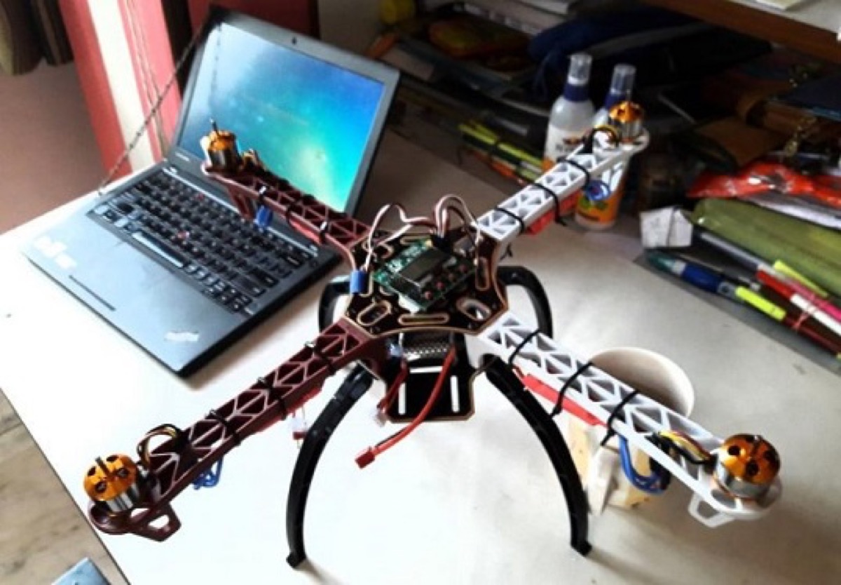
Parts list
- 330 mm quad frame (4 coloured arms) — glass fibre and polyamide nylon
- Mount plates for the 330 mm frame
- 4 × 1000 KV brushless motors
- 4 × 30 A ESCs (electronic speed controllers)
- Two pairs of propellers (clockwise and anti-clockwise) — 10 × 4.5
- 7.4 V–11.1 V LiPo battery charger
- 11.1 V 25C 2200 mAh LiPo battery (3 cells)
- 6″ cable ties
- 6-channel RF transmitter and receiver
- KK2.1.5 multirotor LCD flight controller
- 2 servo motors for camera control
- 4 landing legs
- 2-axis nylon pan/tilt anti-vibration module for the servos
- Glue gun and glue sticks
- Soldering station
- Bolts and nuts
I completed the mechanical assembly first, then the electrical side, then flight-controller configuration.
Mechanical assembly
- Mount each 1000 KV brushless motor on its arm of the 330 mm frame
- Wire each 30 A ESC to its motor so that motors 1 & 3 run clockwise and motors 2 & 4 run anti-clockwise
- Fit 1045R props on the clockwise motors and 1045 props on the anti-clockwise motors
Electrical assembly
- Connect battery output to the KK2.1.5 module
- Connect ESCs to the KK2.1.5
- Connect motors to the ESCs
- Connect ESCs also to power
- RF receiver mapping:
- Aileron → Channel 1
- Elevator → Channel 2
- Throttle → Channel 3
- Rudder → Channel 4
- Servo 1 → Channel 5
- Servo 2 → Channel 6
- Connect a buzzer to the KK2.1.5 for low-battery signalling
Configure the KK2.1.5 flight controller
- Upgrade firmware to the latest available for the board
- Factory reset
- Set self-level / self-control to auto mode
- Load motor layout as X-quad — I used board offset -45
- Receiver test — use transmitter trims so Roll, Pitch and Yaw read zero
- Complete the remaining Misc. setup items for KK2.1.5
- Calibrate the accelerometer (ACC)
- Perform stick scaling
- Run sensor tests (including gyroscope)
- Calibrate ESCs — critical; after calibration all motors should start together
- Arm with throttle, then start and test
- Move / shake the airframe in Self mode and confirm motor speed responds
- Tune PID gains
My PID setup
| Axis | P gain | P limit | I gain | I limit |
|---|---|---|---|---|
| AIL / ELE | 50 | 35 | 30 | 25 |
| RUD | 65 | 20 | 40 | 10 |
What it does today
The quad can fly and capture images/video. Camera pan/tilt is driven on RF channels 5 and 6 via the two servos. Future use cases were still open when I first wrote this up — the point of the build was a controllable platform, not a single mission.
| Cost | ~ ₹10,000 |
| Weight | ~ 1 kg |
| Test environment | Indoor only |
Watch the build
Original video from the project (also on my YouTube channel):
References
- Tags from the original post:
#drone·#quadcopter·#kk215 - Related on this site: Meet my live DIY 3D printer · Meet my 3018 RPi-controlled CNC machine
This piece was first published on 15 March 2018 as Meet My DIY Drone (Quadcopter), and is carried here under Technology as part of the digital journey archive.
Filed under
- Drone
- Quadcopter
- KK2.1.5
- DIY
- Hardware
- PID